Search results
Search for "closed loop" in Full Text gives 37 result(s) in Beilstein Journal of Nanotechnology.
Enhanced feedback performance in off-resonance AFM modes through pulse train sampling
Beilstein J. Nanotechnol. 2024, 15, 134–143, doi:10.3762/bjnano.15.13

- limits the topography tracking quality and hence the imaging speed. The closed-loop controller in conventional ORT restricts the sampling rate to the ORT rate and introduces a large closed-loop delay. We present an alternative ORT control method in which the closed-loop controller samples and tracks the
- advantage of the tip–sample interaction between the first contact point and the maximum force instant. Here, we present a detailed analysis of how the sampling rate and delay in the conventional control method in ORT modes intrinsically limit the closed-loop control of the cantilever deflection and
- -order hold block. Thus, the control process can be represented with a sampler, an integrator, a delay element, and a zero-order hold block (Figure 1E-v.). To analyze the reference tracking quality of the controller, we model a unity gain closed-loop system (further information in Supporting Information


Measurements of dichroic bow-tie antenna arrays with integrated cold-electron bolometers using YBCO oscillators
Beilstein J. Nanotechnol. 2024, 15, 26–36, doi:10.3762/bjnano.15.3

- a few micrometers and the effect of direct electron cooling, which can improve sensitivity in typical closed-loop cycle 3He cryostats for space applications. We study a novel concept of cold-electron bolometers with two SIN tunnel junctions and one SN contact. The amplitude–frequency characteristics


Investigations on the optical forces from three mainstream optical resonances in all-dielectric nanostructure arrays
Beilstein J. Nanotechnol. 2023, 14, 674–682, doi:10.3762/bjnano.14.53

- the surface of a torus along its meridians, which excite a set of magnetic dipoles (MDs) arranged head-to-tail into a closed loop [5]. First proposed by Zel'dovich in atomic physics [6], and existing widely in elementary particles and condensed matter, such as multiferroic materials [7], the TD cannot
- the TD resonance requires the presence of a set of magnetic dipoles arranged head-to-tail to form a closed loop. This kind of TD resonance is usually called magnetic TD. In contrast, the TD response due to a circular configuration of electric dipoles is called electric TD. In this work, we focus only
- on the magnetic TD and then use only TD instead for simplicity. To fulfill the requirement of using a closed loop of magnetic dipoles, two perforating elliptical slots are used with mirror symmetry with respect to the x–z plane across the center of the disk, and each slot is shifted from the disk


Comparing the performance of single and multifrequency Kelvin probe force microscopy techniques in air and water
Beilstein J. Nanotechnol. 2022, 13, 922–943, doi:10.3762/bjnano.13.82

- liquid environments whilst needing the smallest AC bias for operation. Keywords: AFM; atomic force microscopy; closed loop; Kelvin probe force microscope; KPFM; open loop; performance; signal-to-noise ratio; Introduction Atomic force microscopy (AFM) is an enabling technique for the nanoscale mapping
- capable of atomic-scale spatial resolution and nanosecond time resolution under specific conditions. KPFM-based techniques can largely be classified as either “open loop” (OL) or “closed loop” (CL). CL techniques employ a feedback loop to apply a bias to compensate for the electrostatic force (or force
Direct measurement of surface photovoltage by AC bias Kelvin probe force microscopy
Beilstein J. Nanotechnol. 2022, 13, 712–720, doi:10.3762/bjnano.13.63

- tandem lock-in amplifiers, tandem SPV-KPFM [24], which can measure only slow SPV responses on the subsecond time scale because it uses closed-loop DC bias feedback on the millisecond-to-second time scale. Sugawara et al. used two parallel lock-in amplifiers, parallel SPV-KPFM [25], which also detects


Cantilever signature of tip detachment during contact resonance AFM
Beilstein J. Nanotechnol. 2021, 12, 1286–1296, doi:10.3762/bjnano.12.96

- , , and their respective time derivatives , , . Figure 3a to Figure 3d are all plotted with and in the horizontal plane along with , , , and on the vertical axis, respectively. Each closed loop is a steady-state periodic orbit corresponding to an operating amplitude and frequency. Discussion The


Open-loop amplitude-modulation Kelvin probe force microscopy operated in single-pass PeakForce tapping mode
Beilstein J. Nanotechnol. 2021, 12, 1115–1126, doi:10.3762/bjnano.12.83

- various contributions from the probe geometry and imaged features of the sample. In contrast to this, the currently implemented closed-loop (CL) variants of KPFM, either amplitude-modulation (AM) or frequency-modulation (FM), solely report on their final product in terms of the tip–sample contact
- found in many review articles and book chapters [13][20][21][22][23][24]. The majority of the KPFM implementations are in the form of closed-loop systems, with the tip–sample CPD determined from the nullification [25] of either the electrostatic force as in AM-KPFM [1][26] or the gradient force as in FM
- electrical [57][58], chemical [59], optical [60][61], and mechanical [62][63] measurements. Results and Discussion Closed-loop KPFM measurements in two-pass PFT mode The new OL AM-KPFM implementation was tested on a commercially available sample consisting of large Au and Al metal regions deposited on a Si


An atomic force microscope integrated with a helium ion microscope for correlative nanoscale characterization
Beilstein J. Nanotechnol. 2020, 11, 1272–1279, doi:10.3762/bjnano.11.111

- closed-loop sensor data obtained prior to imaging on the AFM scan head. For Figure 2, the AFM image shown was recorded at 300 mHz line rate at a resolution of 1024 pixels and 512 lines and over a scan range of 30 × 30 µm. The imaging mode used was off-resonance tapping (ORT) at a tapping rate of 2 kHz


Measurement of electrostatic tip–sample interactions by time-domain Kelvin probe force microscopy
Beilstein J. Nanotechnol. 2020, 11, 911–921, doi:10.3762/bjnano.11.76

- conventional frequency-modulated (FM-) KFM, the contributions at ωm and 2ωm are detected via lock-in techniques, either at the Δf output of a phase-locked loop (PLL) [12] or by detecting the sidebands of the cantilever oscillation [13]. In closed-loop FM-KFM, a feedback loop is employed to nullify the
- a state observer to continuously recover the full Δf(Uts) parabola, also named Kelvin parabola. The maximum frequency shift Δftopo, the contact potential difference Ulcpd, and the capacitance gradient C′′ are evaluated in real time. When applied as closed-loop technique, the height feedback can be
- performed on Δftopo, where all electrostatic forces are compensated, including the static contribution . So far, recovering and fitting the Kelvin parabola is known as an open-loop technique, the so-called Kelvin probe force spectroscopy [22][23][24][25]. A real-time closed-loop technique has not been


Stochastic excitation for high-resolution atomic force acoustic microscopy imaging: a system theory approach
Beilstein J. Nanotechnol. 2020, 11, 703–716, doi:10.3762/bjnano.11.58

- instrumentation setup is connected to commercial AFM equipment (Figure 1). The following list gives a detailed description of the instrumentation: A SPM, Bruker / Veeco / Digital Instruments Nanoscope IV Dimension 3100 device was used, which was upgraded with a closed-loop x–y nanopositioning stage (nPoint, Inc


Implementation of data-cube pump–probe KPFM on organic solar cells
Beilstein J. Nanotechnol. 2020, 11, 323–337, doi:10.3762/bjnano.11.24

- alternative method that consists in operating the KPFM in standard mode (closed-loop z-regulation and sinusoidal bias modulation) for the topographic analysis and in switching the setup configuration to pp-KPFM with an open z-loop for the spectroscopic acquisition of VKPFM(Δt) curves (Figure 1b and Figure 2
- signal as a function of the pump–probe delay Δt. The topographic scan is performed by closed-loop z-regulation simultaneously with “conventional” FM-KPFM imaging. Before recording each spectroscopic pixel, the tip is stopped. The z-regulation is kept during an initial stabilization delay prior to


A review of demodulation techniques for multifrequency atomic force microscopy
Beilstein J. Nanotechnol. 2020, 11, 76–91, doi:10.3762/bjnano.11.8

- techniques are not discussed in this article. Synchronous demodulation techniques employ a reference oscillator and can be categorized as either open-loop or closed-loop, depending on whether they use feedback to estimate parameters. Open-loop demodulators include the lock-in amplifier and coherent
- demodulator, while closed-loop methods include the Kalman filter, Lyapunov filter, and direct-design demodulator. Performance metrics In a previous work [28], the performance of single-frequency AFM demodulators was assessed by measuring the magnitude of demodulation artifacts and the sensitivity to
- not set the pre-filter to W(s) = 1, instead it utilizes W(s) as part of the design of a desired closed-loop response. In the original work [37] on the direct-design method, a useful and relatively simple design methodology is detailed. Firstly, F(s) is set as meaning the closed-loop equivalent


Deterministic placement of ultra-bright near-infrared color centers in arrays of silicon carbide micropillars
Beilstein J. Nanotechnol. 2019, 10, 2383–2395, doi:10.3762/bjnano.10.229

- wheel (ND). An Olympus dry objective (100×, 0.85 NA) LCPLN-IR with 85% transmission at 900 nm was used. The objectives were mounted on a PI XYZ computer-controlled stage with an XYZ closed-loop positioner with 200 μm travel in each direction and a step size resolution of 1 nm. The samples were mounted


Development of a new hybrid approach combining AFM and SEM for the nanoparticle dimensional metrology
Beilstein J. Nanotechnol. 2019, 10, 1523–1536, doi:10.3762/bjnano.10.150

- %, respectively. The AFM measurements were carried out with a Veeco Nanoman V equipped with an accurate three-axis scanner operating under closed-loop control (hybrid XYZ-scanner with a range of 90 µm × 90 µm × 8 µm). All measurements were performed in air using tapping mode and OTESPA-R3 probes. The cantilever


Charged particle single nanometre manufacturing
Beilstein J. Nanotechnol. 2018, 9, 2855–2882, doi:10.3762/bjnano.9.266


The nanofluidic confinement apparatus: studying confinement-dependent nanoparticle behavior and diffusion
Beilstein J. Nanotechnol. 2018, 9, 301–310, doi:10.3762/bjnano.9.30

- measured surface roughness values. During the measurements described in the subsequent sections, thermal drift and pressure changes may lead to a deflection of the relatively compliant cover glass. These deflections are compensated by implementing a closed-loop system, that registers changes in the


Beyond Moore’s technologies: operation principles of a superconductor alternative
Beilstein J. Nanotechnol. 2017, 8, 2689–2710, doi:10.3762/bjnano.8.269

- dissipation. For this purpose the circuits are made in a closed-loop manner as “timing belts” [75]. Thus, total number of SFQs remains unchanged. However, this imposes certain restriction on the circuit design. It is interesting to note that it was proposed to use nSQUID circuits for the implementation of


Evaluation of preparation methods for suspended nano-objects on substrates for dimensional measurements by atomic force microscopy
Beilstein J. Nanotechnol. 2017, 8, 1774–1785, doi:10.3762/bjnano.8.179

- transducer (PZT) while operating in closed loop [10]. The optical interferometer used for measuring the z-displacement is the National Physical Laboratory’s (NPL) Plane Mirror Differential Optical Interferometer (PMDOI) [11], a homodyne differential interferometer, fibre-fed with a He-Ne frequency stabilized
- the primary route to traceability for dimensional metrology, and in this case it is realized using a frequency-stabilized He-Ne laser [12]. This results in improved accuracy and traceability over commercial AFMs [11]. The measurements were carried out using the AFM in closed-loop, non-contact mode in


A review of demodulation techniques for amplitude-modulation atomic force microscopy
Beilstein J. Nanotechnol. 2017, 8, 1407–1426, doi:10.3762/bjnano.8.142

- or numerically precise low-pass filters, the closed-loop methods employ feedback of the parameterized signal states to eliminate this component. An overview of the demodulator classification is shown in Figure 2. As will be discussed in the course of this paper, each class has distinct properties


Noise in NC-AFM measurements with significant tip–sample interaction
Beilstein J. Nanotechnol. 2016, 7, 1885–1904, doi:10.3762/bjnano.7.181
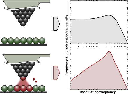
- : amplitude noise; cantilever stiffness; closed loop; detection system noise; frequency shift noise; non-contact atomic force microscopy (NC-AFM); Q-factor; spectral analysis; thermal noise; tip–sample interaction; Introduction Non-contact atomic force microscopy (NC-AFM) [1][2] is an unmatched surface
- this work to parametrise noise in an NC-AFM system. B Frequency response of control loops We briefly outline how we calculate a closed loop response Hxy for a loop containing frequency response functions Hi between the input signal X and the output signal Y. For a more detailed discussion we refer to


![[Graphic 32]](/bjnano/content/inline/2190-4286-7-181-i73.png?max-width=637&scale=1.18182) wit...
wit...

![[Graphic 34]](/bjnano/content/inline/2190-4286-7-181-i75.png?max-width=637&scale=1.18182) wit...
wit...


Single-molecule mechanics of protein-labelled DNA handles
Beilstein J. Nanotechnol. 2016, 7, 138–148, doi:10.3762/bjnano.7.16

- label at the 3’ end of the bead-coupled DNA strand was tethered to a biotin-coated bead, by bringing both beads within close proximity of each other (a few hundred nanometres). The position of this pipette was controlled with a closed-loop piezoelectric element, during force–displacement measurements


Large area scanning probe microscope in ultra-high vacuum demonstrated for electrostatic force measurements on high-voltage devices
Beilstein J. Nanotechnol. 2015, 6, 2485–2497, doi:10.3762/bjnano.6.258

- measurements, such as Kelvin probe force microscopy, scanning capacitance force microscopy, scanning spreading resistance microscopy, and also electrostatic force microscopy at higher harmonics. The instrument incorporates beside a standard beam deflection detection system a closed loop scanner with a scan
- scale of up to 100 μm in lateral and 25 μm in vertical direction under UHV conditions and at room temperature using a large-scale closed-loop scanner. Beside the topographic non-contact AFM mode also contact measurements as well as all major electrical characterization methods (SSRM, SCM, KPFM) are
- into smaller parts and the stages with their directions of motion indicated by the red arrows are visible. The desired scan range of 100 μm in lateral (x and y) directions and 25 μm in vertical (z) direction is realized by a commercial closed-loop scanner (nPoint, NPXY100Z25A). The spatial resolution


Kelvin probe force microscopy for local characterisation of active nanoelectronic devices
Beilstein J. Nanotechnol. 2015, 6, 2193–2206, doi:10.3762/bjnano.6.225

- open-loop method. A PLL can reduce these effects, but then its transfer function needs to be considered as well [27], and the bandwidth must be larger than 2ωm. In closed-loop KFM, the local contact potential difference is found by nullifying the in-phase components of the ωm sidebands (Equation 13
- ''. This strategy avoids normalisation by potentially noisy C'' signals [34], yet changes in C'' do not affect closed-loop performance. We demonstrate this in Figure 6, where we compare step responses of the closed-loop Kalman observer and PI controller. As soon as the gain K drops, the noise level
- increases with a PI controller, whereas the Kalman estimate remains clean. To further elucidate the performance of the controller, we plot in Figure 7 its −3 dB closed-loop bandwidth, normalised to the −3 dB filter bandwidth, as a function of the normalised noise power spectral densities and of state


![[Graphic 33]](/bjnano/content/inline/2190-4286-6-225-i48.png?max-width=637&scale=1.18182) for different modulation amplitu...
for different modulation amplitu...


Development of a novel nanoindentation technique by utilizing a dual-probe AFM system
Beilstein J. Nanotechnol. 2015, 6, 2015–2027, doi:10.3762/bjnano.6.205

- effort to overcome the limitations and problems of current high resolution nanoindentation systems such as AFM-based systems. Different than cantilever displacement measured by optical means, our approach uses a secondary AFM probe that is kept in closed-loop feedback contact with the indenter probe
- holds the sample holder and has a range of 80 μm in all directions. The tuning fork is tuned to its resonance frequency, and either the oscillation amplitude or phase can be used for feedback. Based on the amplitude or phase feedback error, each tower can be independently controlled in a closed-loop
- response curve with an inset including the change of phase over frequency. As the plots indicate, the tuning fork probes have a very sharp resonance curve enabling a sensitive error signal with accurate closed-loop feedback control. Depending on the application, it is possible to configure the system to be


Closed-loop conductance scanning tunneling spectroscopy: demonstrating the equivalence to the open-loop alternative
Beilstein J. Nanotechnol. 2015, 6, 1116–1124, doi:10.3762/bjnano.6.113

- using closed-loop z(V) conductance scanning tunneling spectroscopy (STS) measurements for the determination of the effective tunneling barrier by comparing them to more conventional open-loop I(z) measurements. Through the development of a numerical model, the individual contributions to the effective
- studies have reported on the possibility of obtaining LDOS information by using closed-loop z(V) measurements [5][6][7][8]. Another field of interest is the determination of the work function of materials, through the use of either STS or mechanical break junction (MBJ) measurements. In the case of STS
- fact that the method can be applied by using z(V) spectroscopy means that it can also be used with STM devices that can only measure in closed-loop mode. Model An often used expression for the tunneling current was introduced by Simmons in 1963 [18] and is given as Here I is the tunneling current, ρ


